Glow Plug Plate Material?

connorwhite.online

Active Member
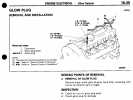
I peeled off my glow plug plate (the sheet metal connecting all 4 plugs electrically) to clean off what I thought was crusted oil, and found that it was actually corrosion (probably aluminum oxide). However I haven't heard the term "rust" applied to aluminum, even though aluminum does in fact oxidize. I consulted the manual and found that an inspection point was to check for rust on the glow plug plate. The plate was so light, I can't imagine it's anything other than aluminum or some electrically conductive alloy. Does anyone know for certain? I'm quite novice with metallurgy.

I ask because I'm thinking of having copper sheet cut to the same silhouette in hopes that the higher electrical conductivity of copper (about twice as much) would be a strong upgrade over the stock plate.
 

Attachments

  • Screen Shot 2021-04-13 at 10.45.38 PM.png
    Screen Shot 2021-04-13 at 10.45.38 PM.png
    514.2 KB · Views: 12
Last edited:
If I were going to do that I think I would use 12awg wire... not sure what the bus bar is made from.
 
If I were going to do that I think I would use 12awg wire... not sure what the bus bar is made from.
That sounds more practical certainly, but the challenge sounds fun. I'm curious if the solid plate (0.080) would deliver the same amount of current as the wire. I like the simplicity of the plate-style as well.
 
The OEM plate is aluminium, and it's big enough to do the job just fine. If it's badly corroded then... what the hell happened to your poor engine? ;-)

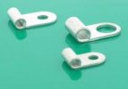
Solid copper would be better (a copper bar with holes in, and shrink tube insulation between the holes), or maybe large gauge copper wire with crimped flag-style ring terminals, though they introduce junctions along the length:

download-1.jpg

The trick is to avoid cutting and joining the wire, the bus bar should ideally be one unbroken length of conductive material.
 
The OEM plate is aluminium, and it's big enough to do the job just fine. If it's badly corroded then... what the hell happened to your poor engine? ;-)

Solid copper would be better (a copper bar with holes in, and shrink tube insulation between the holes)
The aluminum is definitely sufficient, but there's still a bit of room to meddle. I'm reading up on similar research, seems like your idea with the shrink tube would be the real game changer, but I'm not sure how I'd wrap the whole plate. Perhaps an insulated finish I could spray on and sand off of the plug contact points?

I'm finding research that suggests that if you radius the edges of the plate as well, optimal efficiency is achieved.
 
or maybe large gauge copper wire with crimped flag-style ring terminals, though they introduce junctions along the length:
I would use a one-to-many soldered junction using 4 shorter supply wires rather than 1 bus bar type cable (resistance in parallel divides)... you could even solder form the eyelets from the wire itself rather than adding another junction.
Hmm, I wonder if reduced resistance would cause the 6v plugs to burn out sooner; due to getting hotter before reaching the resistance the controller is looking for.
I'm finding research that suggests that if you radius the edges of the plate as well, optimal efficiency is achieved.
IRDT a 12v 80A bus bar is going to be suffering from corona leaks and the like, and DC current doesn't suffer from skin effect. But you could epoxy powder coat the bar as your insulation layer after easing all edges if you wanted... at least it would look nice.
 
Last edited:
Hmm, I wonder if reduced resistance would cause the 6v plugs to burn out sooner; due to getting hotter before reaching the resistance the controller is looking for.
Oof, hadn't even considered the load that'd place on the plugs. This could be an expensive experiment!
But you could epoxy powder coat the bar as your insulation layer after easing all edges if you wanted... at least it would look nice.
This is along the lines I was thinking. Protolabs offers powder coating, so I could use a tiny dremel sander to take it down to bare copper at the plug contact points.

Out of curiosity, my glow plug wire is on cylinder 3, and it seems a bit contradictory to what I "know" about current flow. Should it be on cylinder 4?
 
Oof, hadn't even considered the load that'd place on the plugs. This could be an expensive experiment!
TBH, I doubt you're going to be able to make enough of a change to really have any measurable impact on the GP's.
This is along the lines I was thinking. Protolabs offers powder coating, so I could use a tiny dremel sander to take it down to bare copper at the plug contact points.
I would use an end mill cutter in a drill press (actually, I have a mini-mill).
Out of curiosity, my glow plug wire is on cylinder 3, and it seems a bit contradictory to what I "know" about current flow. Should it be on cylinder 4?
Nah, a bus bar is essentially a bunch of parallel connections; just not equidistant. It makes the most sense for the supply wire to connect in the center of the bus bar; but it's insignificant enough to not really matter.
Out of curiosity I measured the resistance across a 4in length of copper clad steel, a 4in length of aluminum bar, and a 4ft length of aluminum bar; and any difference was less than my fluke meter can measure... hmm, I do have a high resolution bench meter...
 
Top