Alternator wiring question?

sck_nogas

Moderator
Staff member
Background: I have a D4BF engine, so I have 2 types of alternator connections have been grafted to the existing wiring harness, plus the two thick wires that bolt to the alternator output. This weekend, whilst changing out the alternator, the copper crimp eyelet terminal broke. So, I needed to crimp on a new one. No biggie, but as I did I noticed an "extra" wire and have NO idea what this is for?

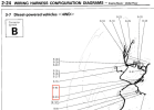
So, here's the wiring diagram.
Charging Circuit.jpg
With the colors coded in Blue in the image, and the FOUR wires that connect to the alternator.​
But, this is what I have in that wire bundle...
alternator_wiring - 1.jpeg
4 wires.jpg
Blue, red/white, 2 thick white and some weird yellowish white with a female spade connector?​
And the after picture with my new crimp eyelet terminal (and alternator boot) installed.​
alternator_wiring - 2.jpeg

Any guesses as to where and WTF this wire is for?
 
Last edited:
That's not a factory connector, temperature sending unit maybe? Must be something down near the alternator that it went to!
 
Okay... Now I'm really frustrated!

I finally got a break in the rain so I could put the connections onto the alternator, and get my Delica back running. (Grrrr, really want a garage/shop I can work in!) So, I clean the terminals up real pretty and slap on dielectric grease and then fish the wire bundle down to the alternator. Slide under with my trusty 13mm socket wrench and... I can't connect the battery<->alternator crimp. It's 1 inch :mad: o_O too short! No matter what I do, I can't get any more slack.

So, I go to the wiring diagram (already in the first post) and see that there are two connectors, I track the wiring bundle into the air filter compartment and there are two connections.
wiring - 1 (1).jpeg

My issue is that I can't see how to disconnect the B-83 connector, and it's taped and connected to the wiring harness so I can't see how to open/disconnect the shield. Any thoughts on how to open it?

Plus, I went to see if I could see if I can find a replacement part of the wiring harness (in case I broke some 30 year old brittle plastic), but can't seem to find what part number would be used for this. Closest I can find is MB802255 (aka Harness, Engine) but that's the entire harness, and can't see if it includes those connectors

Anyone got any ideas, before I just cut the wires and solder in a 2 inch extension in the middle of the bundle?
 
@sk66 @Growlerbearnz @Kellyn (and other's in the Delica Brain trust) :p
Anyone got any ideas on how to disconnect the B-83 connector to see how to replace those wires?
Anyone got any leads on what part number that section of the wiring harness is?
Anyone got any thoughts on how best to (or not to) splice those wires to gain a couple of inches?
Anyone parting out a Delica and can sell me that section of the wiring harness?
 
For that B-83 connector, it looks like a splice kit within a box. I've seen similar ones that had a bolt connection inside. I'm not sure if that's factory or not, could be something totally different. From what I can see in the picture there is a clasp on the top side and the hinge to open it is on the bottom. I could run out and look at the van and see if I have the same but it has 8" of snow on it and I'm nice and warm right now!

1640880994688.png

As for splicing the large gauge wires. If it were me, I'd solder them and use heat shrink tubing to seal them up. Those carry a lot of amps so you want a good connection and you want to use good quality automotive wiring that is the same gauge. If you are unsure of soldering technique:


Always fun working on wiring that someone has messed with in the past!

Good luck
 
I think you have the junctions identified correctly, and the engine harness section as well (although it will only have 1/2 of the connection). I believe B83 is a side hinged cover and not a connector per-se.

I think the easiest way would be to cut the wires and splice in extensions. The neatest/best answer is probably to make mini harnesses/extension that can plug in in-between... but that may well be more work/expense than it's worth.
 

Attachments

  • Screen Shot 2021-12-30 at 11.22.43 AM.png
    Screen Shot 2021-12-30 at 11.22.43 AM.png
    659.1 KB · Views: 15
For that B-83 connector, it looks like a splice kit within a box. I've seen similar ones that had a bolt connection inside. I'm not sure if that's factory or not, could be something totally different. From what I can see in the picture there is a clasp on the top side and the hinge to open it is on the bottom. I could run out and look at the van and see if I have the same but it has 8" of snow on it and I'm nice and warm right now!

View attachment 14983

As for splicing the large gauge wires. If it were me, I'd solder them and use heat shrink tubing to seal them up. Those carry a lot of amps so you want a good connection and you want to use good quality automotive wiring that is the same gauge. If you are unsure of soldering technique:


Always fun working on wiring that someone has messed with in the past!

Good luck
You were right! I've ordered more 4 gauge wire (only have 12/14 gauge at home). So, to document...
wiring - 1.jpeg
That's the connection.
 
Make a ~2” wire with ring terminals on each end. Bolt to each existing ring terminal with short bolts and then heat shrink.
 
I would just replace the whole two white wire ring terminal link from the splice bolt to the new one you just added (sorry!) and make a longer one that works. The less connections the better.

Edit, just read the 4 gauge wire... wow, thick stuff!
 
You were right! I've ordered more 4 gauge wire (only have 12/14 gauge at home). So, to document...
You have to be careful, some conversion charts are in mm of diameter (5mm dia = 4awg). But the wiring diagrams are annotated by sectional area in mm² (5mm² = 10awg). Sometimes the conversion charts don't really say which metric convention they are using...

Screen Shot 2022-01-01 at 10.37.58 AM.png
 
Last edited:
You have to be careful, some conversion charts are in mm of diameter (5mm dia = 4awg). But the wiring diagrams are annotated by sectional area in mm² (5mm² = 10awg). Sometimes the conversion charts don't really say which metric convention they are using...

View attachment 14999
Considering both of the wires are labeled AVX5-W, that would lead me to believe 5mm and if I caliper them...
wiring - 1.jpeg
Outer diameter is 5mm...
wiring - 2.jpeg
And the wire diameter is 4.2mm (or so).

So, I think 4 gauge is sufficient.
 
Considering both of the wires are labeled AVX5-W, that would lead me to believe 5mm and if I caliper them...
5mm² in area... you can't measure that directly with a caliper (conversion chart says it should be about 2.5mm in core dia).
So, I think 4 gauge is sufficient
Definitely sufficient ;) ... 4awg would be labeled as ~20mm² on the wiring diagram (e.g. the primary battery cables for the gas engined vehicles).

Edit: I just noticed that the terminal attached to the other end is labeled 8awg-5/16", and it's oversized...
 
Last edited:
You need to account that you are using braided wire which is going to appear a little bigger than a solid core wire. 4 is really big stuff like sk66 mentioned, you wouldn't need to double up with that, just a single wire. You might need to get some large connectors to work on that wire size.
 
5mm² in area... you can't measure that directly with a caliper (conversion chart says it should be about 2.5mm in core dia).

Definitely sufficient ;) ... 4awg would be labeled as ~20mm² on the wiring diagram (e.g. the primary battery cables for the gas engined vehicles).

Edit: I just noticed that the terminal attached to the other end is labeled 8awg-5/16", and it's oversized...
You need to account that you are using braided wire which is going to appear a little bigger than a solid core wire. 4 is really big stuff like sk66 mentioned, you wouldn't need to double up with that, just a single wire. You might need to get some large connectors to work on that wire size.

Well, I've rebuilt the cable with the 4 gauge wire, I had gotten 8 gauge wire but it was less flexible.
wiring - 1.jpegSo, here's the new wire harness to reinstall. Also re-did the Oil Pressure wire.
wiring - 2.jpeg
Now to install it back in and get driving again! :)
 
That's interesting; I was assuming they used dual cabling because it was more flexible (or flatter)...
The only 8 gauge wire I could find locally (in white) had fewer (but thicker) strands in the wires, thus they were less flexible than the 4 gauge wire I got.
 
Nice! If it's not too late, maybe heatshrink that oil pressure connector to give it a bit of strain relief, they always break where the wire enters the connector.
 
Top