Finished! Rebuilding the OEM alternator... (long w/ pics)

sk66

Moderator
Staff member
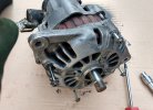
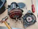
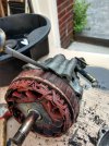
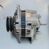
Finally got most of the parts together to do a full rebuild of the OEM alternator; parts needed:

  • Seals ME700547 (2ea)
  • Bearings MD611474, MD611476
  • Regulator MD611668
  • Rectifier MD611599
  • Crush Washers MF660063 (2ea, 4 if replacing the line)
  • O-ring ME700951

Unfortunately, all of these parts are unavailable OEM; so I sourced the highest quality parts I could find (AS-PL europe, and NSK japan bearings). Total parts cost ~ $100-$120.
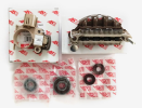
1696442324216.png

This is really about rebuilding the alternator, but I'll quickly cover the basics of removal/install. First step in removing the alternator is gaining access...
Remove the driver's side engine cover and engine stone shield/bash plate- ~ 15-20 minutes.

Consider removing the radiator... the 30 minutes it takes will make access a lot easier/quicker; and you might wind up removing it anyway. I didn't, and because I didn't, I used a variety of ratchets, extensions, ratcheting box wrenches, and contortions... going back and forth trying to find "the right 12mm combination" wasted a fair bit of time.

Removing the alternator
  • Start by disconnecting the battery... just the ground is probably adequate; I disconnected both and covered the positive post (the connection of concern is the alternator fusible link).
  • Next, back off the tensioner lock bolt, slack off the tension, and remove the bolt that secures the bracket to the alternator (12mm)... the rest of the work can be done from below.
  • If you want more room to work; jack up the front of the van and support it on jack stands (or run it up on ramps before beginning).
  • Start disconnecting stuff... beginning with electrical; disconnect the 2 wire plug, the oil pressure light wire next to the alternator, and the single large wire (10mm). If the wire end rotates with the nut, jam a flat bladed screwdriver next to it to prevent the rotation... there is a second 12mm nut behind the wire terminal, but it's about impossible to get a wrench on it. With those 3 connection undone, move the harness out of the way.
    (*as a side note... if you find the ubiquitous decayed electrical tape, investigate; I found an exposed solder splice that exists for no apparent reason)
  • Use a flat bladed screwdriver to push the vacuum lines off (no need to remove the spring clamp first).
  • Loosen the locking nut (12mm) on the alternator pivot bolt and remove the belts from the pulley... you can't remove the bolt with the oil return line installed.
  • Remove the oil lines (feed banjo 17mm). Stick the end of the feed line up somewhere so it doesn't keep dripping (residual line oil). If either the feed line or return line is hard, or shows any sign of decay, replace it. And if replacing the return line, move the clamps out of the way and cut the line out with a razor knife... it's far easier than fighting with that thing. The vacuum pump will drain some oil, and probably some more at the end when you pull the alternator out.
  • Next, remove the pivot bolt. I was able to use a short punch (centered by the backed off nut) and a hammer to drive the bolt back; then I was able to get a flat bladed screwdriver behind the head to pry it out farther, and then pull it the rest of the way out. If it won't move I suggest removing the radiator and using the bearing puller to push it out. Don't have one? Get a $15 puller; you're probably going to need it for the alternator rebuild anyway (or some other task in the future ;) ).
  • Pull the alternator out and put it in a container to collect the remaining oil in the vacuum pump.
Total time to remove the alternator ~ 1.5 hours, including the access panels. I did sacrifice the oil return line and I wasn't planning on that... so I'm waiting on a replacement.

Next, disassembling the alternator...
 
Last edited:
There's a few "specialty" tools you will want/*need:

  • You will probably need an inexpensive bearing puller; if you get the one I linked in the first post you will need two m6 x 1.0 bolts that allow it to clamp onto smaller diameter bearings/pulleys (fully threaded is probably the most versatile).
  • A 1/2" impact wrench will make removing/installing the pulley nut easier... I have a relatively cheap Ryobi cordless.
  • *A 24mm socket.
  • *A strap wrench (or a large bench vise).
  • *A fairly heavy duty soldering iron/gun (and electronics solder).

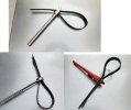
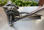
I have an old HD strap wrench; I don't recommend the cheap plastic ones. And I wouldn't generally recommend a chain wrench instead (I have one of those as well). If you don't have a strap wrench there's a couple DIY options. The first is to run a belt through the end of a large box end wrench (like 1.5")... I don't own box wrenches that big; but my wife does! Another option is to run the belt through a pipe wrench/ford wrench or similar. All three are shown using a section of timing belt which is especially useful for holding timing pulleys as well... sometimes the smooth side works better.

strap-wrench.jpg
 
Disassembly: (take pictures to make sure you can put it back together right)

  • Start by removing the vacuum pump (3- 8mm bolts)... I didn't want to as mine wasn't leaking, but it made a mess leaking oil while working with it installed (even after I let it drain). And I wound up removing it later anyway. So do it now and set it aside in something to contain the leaking.
  • Use the strap wrench and 24mm impact to remove the nut securing the pulley. A 1/2" drive breaker bar or HD/long torque wrench could be used as well... most 1/2" drive ratchets won't have enough leverage.
  • Remove the front case retaining bolts (4- 8mm). You can also remove the four JIS screws, but you don't have to do that now (I did).
case-screws.jpg

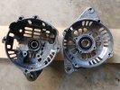
  • Remove the front cover. This is going to be a little difficult as you are fighting against a pressed bearing and the cover is probably partly bonded to the stator due to dissimilar metal corrosion. There's several places around the case where you can get a flat bladed screwdriver in to pry them apart... at all four screw passages on the front cover. You can also lightly hammer on the heavier lugs and on the shaft (use the nut to protect the threads). Use patience and work it off in small increments working your way around... it will come apart. You can see a significant amount of white aluminum oxidation/corrosion on the stator (it's not just paint loss).

    front-case-removed.jpg
stator-case-separation.jpg

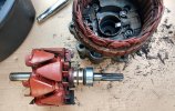
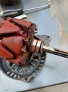
  • Remove the rotor shaft. Some repeated light taps on the pump end of the shaft should free it. There's about 1/2" of pressed bearing interface you are freeing it from. It may come out with the bearing still on the shaft, or stuck in the case. On mine the front stayed in the case and the rear stayed on the rotor (I believe that is typical).
slip-rings.jpg

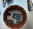
That rear slip ring is pretty ugly... the wear isn't particularly deep, but it's uneven/scarred. In this picture you can see the three screws which hold the stator, rectifier, and regulator assembly in place... and yes, it is an assembly.

  • Using a multimeter, test the rotor coil for resistance between the two slip rings; you should see around 3-4 ohms. Then test for resistance between the slip rings and the rotor shaft; there should be none (OL).
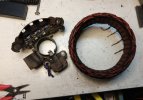
Now it's time to desolder the stator from the rectifier. Use a pair of pliers or a screwdriver to lift the wires free once the solder flows. Then remove (pry) the stator from the rear case, and remove the rectifier/regulator assembly.

statpr-separated.jpg
  • With the stator disconnected, test for continuity between each pair of lead wires; you should see 0.5 ohms or less. Then test for continuity between each pair and the stator plates; there should be none (OL).

    The rotor and the stator are the only things I'm not replacing, so they need to be in good condition. They can be replaced or rewound, but it's not commonly required. To be honest, I didn't even test them... hopefully that wasn't a mistake.
 
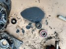
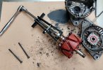
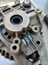
  • Finally, drive the seals and bearings out of the cases as required... there's two seals in series at the rear creating an isolation chamber in case the first one leaks... mine was pretty ugly in there. Use the bearing puller to remove bearings from the rotor shaft. The bearings actually felt ok.

bearingsSeals.jpgbearfing-puller.jpg


Now it's time to clean things up... dish soap and warm water is best. Avoid solvents, you do not want to ruin the field winding insulation. Scrape/brush any corrosion from the stator/case interfaces... a small flat screwdriver works well. Brush/scrape any loose stuff from the stator's outer face in preparation for repainting... avoid scraping the windings (although they are not delicate). Repainting will slow/prevent the corrosion that is otherwise problematic. Let it dry... I threw it in the oven at 200˚f for a few hours and then let it sit in there overnight. Paint the stator (rustoleum/krylon/whatever). You do not have to worry about overspray on the windings... it's just more insulation. I used the oven at 200˚ again to speed cure/harden the finish.

Next, reassembly:
(do everything in reverse ;) )
 
@prayforsurf0 this thread comes just in time :p

Ahh, just a bit late actually. I FINALLY got mine back yesterday and will be reinstalling it today. I really don't like letting other people handle repairs and the like on my rig.

Nonetheless, thanks for this detailed thread @sk66

The person I used to rebuild my alternator struggled to source the rectifier. He said he measured mine and ordered a new one with similar dimensions. Apparently he still had to modify it a bit to make it fit right.
 
The person I used to rebuild my alternator struggled to source the rectifier. He said he measured mine and ordered a new one with similar dimensions. Apparently he still had to modify it a bit to make it fit right.
Yes, the specs for the rectifier that make it compatible/interchange does not include the little plastic shield. That shield isn't actually required on this alternator, so I just removed it. I did try to modify it with heat forming/etc... it was pretty pointless.
 
Reassembly:

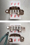
First thing is to modify the rectifier by removing the plastic shield. Unfortunately, I have not found a replacement rectifier that is 100% compatible with the Mitsubishi alternators. This rectifier is specified as a direct replacement for the OEM part, and the critical specs do match; but in this case the plastic shield prevents the rectifier from mounting correctly.

But luckily, the protective shield isn't really needed. The primary purpose of the shield is to prevent the winding leads from rubbing on the metal alternator housing and causing a short. But there is *a lot of space* between the winding leads and the housing on these alternators. And the leads are large diameter solid core of short length... they are not going to vibrate/move and make contact. The secondary/lesser purpose is to prevent something from physically jumping the gap and causing a short... it would also have to wear through the winding's insulation for that to happen. And I'm not talking about water... water can jump the gap simply by going around the shield (it still won't short out though).

So, simply remove the shield with snips or a knife... (you do not need to be as neat/thorough as I was).

rectifier.jpg

If you wanted, you could remove the shield from the original rectifier and attach it with the single mounting screw... I did not. IMO, there is nothing for it to really damage if you do, but it is much more likely to vibrate and move with one end being free. I suppose you could leave the fixed end on the rectifier and try to glue/melt the two together; but again, not required...
 
Next is to prepare the back housing by installing the rear seals and bearing. Both seals install in the same orientation with the flat face inwards... I almost always use a touch of grease when pressing things together.

For the bearing I used a large socket a little smaller in diameter, but still resting on the outer metal race... you can use just about anything that can meet the same requirement (PVC tube, metal pipe, wooden dowel/block, etc). Place the housing on something like a piece of wood to protect it, and then drive the bearing into place using fairly light, but firm, hammer strikes... don't use more force than you absolutely have to. Of course, a proper machine press could be used as well ;).

This might seem a little odd as the rear bearing has to seat in a specific location on the rotor shaft... you could seat the bearing on the shaft instead at this point. If you do it that way you will need a length of pipe that very closely matches the bearing's inner race, and a way to brace the rotor shaft to help ensure you are driving it squarely. Instead, I'm going to use the housing to press the rotor/bearing into place later on.

Might as well set the front bearing while you're at it...

new-bearings.jpg
 
Reassembly of stator/rectifier/regulator:

This is fairly straight forward... attach the rectifier and regulator into the rear housing with the three screws; rectifier first as the regulator has a solder contact that needs to overlay. And then install the stator onto the housing so that the four leads closely line up with the contacts on the rectifier... it does not need to be fully pressed into place at this point.

Next, bend the four stator lead wires so that they are in the correct positions on the rectifier, making sure they are well clear of the metal housing. Then solder the four leads to the rectifier, and the rectifier to the regulator.

new-regulator.jpg

In the picture above you can see that the brushes are held in the retracted position with a retaining pin... this allow the rotor to be installed and the brushes/slip rings to line up. But we need to replace it with a much longer one that can be removed after assembly. I used a length of solid core wire... pretty much anything can be used (twist tie/paper clip/etc).

In this picture you can see the replacement pin extending outside of the housing so it can be removed later.

brush-pin.jpg
 
Now it's time to finish the reassembly.

If your slip rings were in bad shape you have a few options. I was able to chuck it up in my benchtop mill and turn them down. I started with a file, then 220 grit wet/dry sandpaper, finishing with 600 grit. I didn't have the ability to use machine supported cutters like a proper lathe, which would be safer and more precise; I used the file/paper freehand instead.

But the shaft is 18mm (.7 in) and will not fit into most 1/2" drill chucks. You could use the nut and 24mm socket to spin it; but you would need some way to support the free end. Maybe a hole through through a piece of wood and using the old bearing to space the rotor off. Or if you have a drill press you can mount a point (sharpened bolt) to the table and use it as a vertical lathe using the nut/socket... the shaft already has a centering dimple in it. Whatever you do, if you are spinning it, go slow and careful... you are working very close to those cooling fins and they will happily grab whatever tool you are using. Place the file/block/whatever on the side moving away from you so that it pulls the tool away from you should the fins catch it... and hold the tool lightly so it's free to leave rather than pulling your hand in (if hand holding as I was). Alternatively, you can just spin it by hand (full rotations, not oscillating back/forth).

You could also take it to a local shop that can turn them down on a lathe.
As a last resort you can just reassemble "as-is". It's like putting new brake pads on w/o resurfacing the rotors, it will probably work fine... people do it all the time. And you can buy a replacement if they are really bad.

Here's the slip rings after cleanup (I didn't remove every last mark).

slip-rings-2.jpg


  • Insert the rotor and mount the front housing... make sure to alight the mounting ears and bolt holes correctly; then press as firmly as you can... I set the rear housing on a couple scrap pieces of 2x4 on edge so I could put all my weight behind it w/o pushing against the rotor shaft.
  • Do not forget to install the front bearing retaining plate (4 JIS screws) and the rotor spacer before mounting the front plate... I didn't show/specify them before.
  • Install the 4 mounting bolts loosely (8mm), they should all have enough length to grab securely. Then slowly tighten them in a criss cross pattern to press everything together.
  • Once they are all fully seated you will probably find the rotor is jammed up or extremely stiff to turn. Put the nut on the rotor shaft to protect the threads and give the end of the rotor shaft a few firm taps with a hammer. That will finish seating the rear bearing and restore the small amount of free play required for the rotor to spin.
  • Reinstall the Pulley, lockwasher, and nut using the strap wrench and impact gun.
    I was unable to find any manual/specs for the alternator itself. I did reference the manuals general torques table for an 18mm bolt and it's anywhere from 101 ft lbs – 289 ft lbs which seems excessive for this application; so I just verified I had a minimum of 50 ft lbs torque, which is a pretty typical number for this application (e.g. Bosh alternators).

    I find it is easiest the jam the strap wrench against a solid surface when trying to set/break torque with a manual wrench.

    torque.jpg

  • Pull the pin to allow the brushes to contact the slip rings and recheck that the rotor spins nicely with no binding or noises; it should be fine (it won't be "free spinning" though) .

    reassembled.jpg
This is where the project sits for now as I am waiting on a new vacuum pump o-ring and oil return hose I wasn't planning on needing. Total time for the teardown and rebuild is ~ another 1.5 hrs (not including drying times).

An alternator rebuild at a shop will typically cost anywhere from $250 – $350... towards the low end if they just replace the regulator, and towards the high end if they do everything as I did. And you don't know what quality of components were used or work done.

Doing it yourself is like paying yourself ~ $150/hr; or at least it pays for a couple new tools and you learn a thing or two in the process.
 
Last edited:
I take it your not married or living with a life partner ?? Because my wife would KILL me if I put a freshly painted car part in the oven to cure the paint faster :eek:
 
I take it your not married or living with a life partner ?? Because my wife would KILL me if I put a freshly painted car part in the oven to cure the paint faster :eek:
My wife is fine with car parts going in the oven... she was an A&P helicopter mechanic; she understands. She's less happy about meats... she's also vegetarian.
 
Finally got around to finishing the rebuild... it can take quite a while to figure out the specs and source suitable replacement parts.

FWIW, the o-ring that seals the vacuum pump to the alternator is 25mm x 2mm, the o-ring that seals the vacuum pump case is 72mm x 2mm (I didn't replace this one), the oil return hose is 15mm ID x 23mm OD x 120mm OAL, and the oil feed hose copper washers are 10mm ID x 16mm OD x 1mm TH. The OEM (unavailable) o-rings were nitrile rubber, I sourced viton o-rings.

This post is primarily about reinstalling the alternator... and once again; I was second guessing not having just pulled the radiator in the beginning. But at least this time i already knew what worked to gain access to the bolts.

But first is to finish reassembling the alternator by mounting the vacuum pump. Start by placing the vacuum pump on a flat surface with the o-ring groove facing up. Set the new o-ring into place (after removing the old one) and then lower the alternator onto the pump. You can use a little grease to help hold the o-ring in position, but I didn't find it necessary. It is possible that the pump could have been reinstalled using the old o-ring and sealed just fine... I just didn't want to take the chance given the cost vs time/hassle equation.

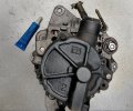
The pump shaft to gear spline interface is very tight and the pump may not want to seat completely by hand. Next is to install the three mounting bolts. They are 5mm (threads) with unmarked heads and the standard torque tables give a maximum of 5 ft lbs... all I know for certain was that it wasn't hard to remove them with a 1/4" drive ratchet. So I went "snug plus", but this is also the only place I used loctite (blue). If the vacuum pump were to come loose it would create a major oil leak that could quickly destroy an engine. Clean the bolts/holes with degreaser so that the loctite bonds (the JIS cross drive bolts hold the pump together, leave them alone unless replacing the larger o-ring as well).

pump.jpg

Next is to clean up the pivot bolt of any corrosion for reinstallation. I put some anti-seize in the entry side of the pivot mount (engine bracket) as well as in the entry side of both ears on the alternator... that prevents the first ear from scraping most of it off of the bolt. Align the alternator and spin the bolt into place; spinning it helps it spread the anti seize rather than just pushing it through. Do a good job of cleaning any excess that is pushed through, and make certain to not get any on the belts or pulley. Install the nut loosely; might as well put the belts back on the pulley while you're there.

The next PITA is installing the new oil drain line... to make it easier, place the hose in boiling water for several minutes to help soften it up; and install it as hot as you can tolerate handling it. It took me several attempts to get it seated well at both ends. I do not recommend screw type band clamps; the OEM style spring clips are more than sufficient in this application... put them on the hose before installing it.

Next is to just reconnect everything (plug, oil pressure warning light, main cable) and vacuum hoses; put the spring clamp in place at the end of the large vacuum line before installing it... it saves a step and some hassle. The main cable's 12mm nut is torqued to 15 ft lbs (14-18/20-25nm). Install the oil supply line with new gaskets (copper washers) and torque to 12 ft lbs (10-14/14-19nm)... the old gaskets can be annealed and reused in most cases if you prefer.

Next reinstall the tensioner bracket to the alternator... pretty big PITA with the radiator shroud and coolant hose in the way. I even had my wife try with her smaller hands; she gave up after some cussing... I eventually got it with some contortions using a backhanded left hand technique.

And now it is time to set the belt tensions to ~13mm play (13-16mm used belts/10-13mm new belts). Then torque the lock bolt (mounting bolt) to 15 ft lbs (14-18/20-25nm). I find it is better to over-tighten the belts and then back the tension off to the correct setting.

Next torque the pivot bolt to 30 ft lbs (25-40/35-55nm). This is actually quite high for a bolt/nut this size; it felt excessive... I even stopped and tested the torque wrench I was using against another one just to make sure. I'm not surprised that it coming loose and wallowing out the pivot holes is so common; because torque wrench neglect is a real problem.

Finally, start the engine and check for proper charging. Shut it down, verify belt tensions, and look for any oil leaks. Now I can get back to the exhaust brake project!

Because sourcing the parts was pretty involved, and because one-off shipping is also excessive, I have put together complete rebuild kits (10 sets ea). The kit with regulator, rectifier, seals, and bearings is $105. If you also need/want the vacuum pump seals (2 orings and 2 copper washers) they are $17 a set (shipping is included). I also have new vacuum pumps as well (I opened a wholesale distributor account with AS-PL).
 
Nice!

I'm wondering if one wanted to upgrade a 75A alternator to 100A/150A is that modification done to the stator, or does it include a different rectifier also? Also wondering if the kit you're offering is compatible with 1989-1999 Delicas (internals are the same, but the housing and such differs a bit). Thanks.
 
I believe you would need a different stator in order to increase the amperage... the number of coil windings determines the maximum current an electromagnet can generate. Might also need a different rectifier with larger diodes; but I think that would be the easy part.

My van is a '91, but I did more research based on your question.
The bearings and seals match all years, even though the part numbers changed. The rectifier and regulator are compatible for '89-94. I'm pretty sure they are also compatible with later years, but the style changed '94-99. I can also get the correct style of regulator/rectifier for the later year models with just a little notice, and offer the kit at the same price.
 
Very comprehensive and well written. Surprised the OEM bearings are NLA because they were most likely made by Koyo or NSK anyway.


Love your work SK
 
Surprised the OEM bearings are NLA because they were most likely made by Koyo or NSK anyway.
I'm pretty sure it's just a case of changing part numbers... and the old number is no longer maintained. E.g. in 94 they changed the rear bearing part number to MD618731 even though it's the same size/specs; there's a few of that part number around yet.
 
Top