D4BF Engine Swap

A good amount of progress this weekend. The parts are piling up. This is a fun but nerve-wracking project and I can tell you this job is not for the faint of heart and would seem all the more daunting without Growlerbearnz's engine install thread, http://www.delica.ca/forum/viewtopic.php?f=94&t=18908 (it would be like flying blind) and my buddy Tom giving me a hand.
IMG_7673.JPG
Fluids drained, battery disconnected, radiator removed. Hoses and wiring loom disconnected, power steering pump and compressor moved out of the way. Is it too late to put it all back???
IMG_7674.JPG
Left-front side and transmission bell-housing supported.
IMG_7683.JPG
Hoist attached to lifting points and tensioned. We probably could have still taken up one more link in lifting chain. We finally removed the engine mount and bell-housing bolts.
IMG_7684.JPG
It didn't come apart smoothly but did finally separate which probably means things were a little misaligned. After separation we eased the engine forward with just barely enough space front-to-back to raise it vertically.
My buddy Tom, helping finessing the beast out of the engine bay.
IMG_7686.JPG
And then we had like a millimeter or two above the boom and below the sump to come clear, but it didn't hang up.
IMG_7689.JPG
Unfortunately we did disturb the torque converter and ATF came rushing out. So we will need to replace that properly so as not to potentially damage the tranny.
IMG_7690.JPG
My neighbor is going to lend me his engine stand for the old engine and then the new one will go on the hoist for the changeover of parts. It's way dirtier than it looks here in this pic. The turbo side is absolutely disgusting. (The turbo shit itself a few months ago driving up to the ski basin, so the Delica has been sitting, waiting for the swap. Didn't make a whole lot of sense to spend another $1K on a new turbo with a complete new engine sitting in the wings.)
IMG_7692.JPG
Shame I won't be needing this spanking new clutch pack and flywheel. I'll figure out a price and put them up on the Parts for Sale.
IMG_7703.JPG
Swapped over the original oil pressure sensor, bellhousing spacer, flexplate and a/c pulley. The sump, dipstick, some small brackets and a/c bracket need to wait until the engine is in the air. I think I'll keep the new alternator and install new plugs.
IMG_7705.JPG
I think I'll tackle cleaning the engine bay next. Once I get the engine stand I will swap the sumps. That will be a messy job. There is a small list of parts I'll need to order as well. I'll post a pic of my list once I feel it's complete.
 
Last edited:
Tonight's projects were cleaning the engine bay and removing the sump and oil pickup from the old engine.

Sprayed the engine bay heavily with degreaser and then rinsed it with high pressure water.
IMG_7734.JPG
Moved on to the oil pan, using a gasket scraper with flat blade to break the silicon sealant bond with the engine case. No gasket here, just what looked like Ultra Grey silicon sealant.
IMG_7735.JPG
No sludge or surprises in the bottom of the pan. It was quite clean actually...in a dirty, filthy diesel kind of way.
IMG_7736.JPG
Kinda cool being able to suddenly see the heart of the beast.
IMG_7737.JPG
Cleaned off the silicon residue from the oil pan mating surface and then thoroughly cleaned the pan inside and out.
IMG_7740.JPG
I may throw some high-temp black paint on the outside of the oil pan. The pan on the new engine is glossy black. Shame it won't work in the Delica. It is basically configured in reverse with the deep part of the sump to the front.
IMG_7741.JPG
Removed oil pickup tube and cleaned it up as well.
IMG_7742.JPG\
I also removed the alternator from the old engine and cleaned it up and put it up on the shelf. Never hurts to have an extra alternator laying around. I believe it is 75 amps.

After I get an engine stand I will put the new engine on the lift and exchange the oil pans and other parts.
 
My old oil pan had a similar dull black gunk coating, I think it was baked-on oil and dust residue. I was able to clean it off with gasoline and a rag (and a fair bit of elbow grease). It came up almost as shiny as the new oil pan.
 
I was asked about the water line feeds for the redesigned turbo the d4bf uses. Here are some pics of how it was done.

The lines are connected on the outside and inside of the turbo with banjo bolts.

The outside line T’s into the hardline coming off the water pump (somewhere behind the intake manifold) that runs around the back of the engine and connects to the heater hose.
6E0B56DF-F2B3-4B0C-994C-AAAD0D6E0586.jpeg

The inside connection is an additional line that also runs around the rear of the engine and T’s into the bottom of the upper radiator hose connection on the engine.
06575D8D-16D6-4742-8549-D37350EBDEA5.jpeg

8FF2CABB-6812-4B9F-969F-C7668D00C96A.jpeg

9C30986C-8C33-4C12-8EB2-FEFD5923E9B5.jpeg

I imagine these additional parts can be gotten if you have a turbo with both oil and water cooled connects in the same locations It would also probably not be too difficult to just fabricate them.
 
Last edited:
The guy at Hyundai who sold me the engine recently sent me this link to workshop and owners manuals for one of their vehicles that uses the D4BF engine. Probably some useful info in the workshop manuals, although the owners manual is in Russian.

https://manuals.co/workshop/hyundai/h-1

Not a ton of progress this week, but did get around to ordering more parts I needed for the install. I also sprung for an engine stand so that I can begin swapping over the oil pans. Flipped the 4D56 upside down and the remainder of the coolant poured out from the water pump all over the floor.
IMG_7901.JPG
I've also decided to have the 4D56 pan and sundry other parts ceramic coated before they go onto the shiny new D4BF. Initially I thought about having the parts powder coated but ceramic coating is marginally more expensive and far more durable in high temperature applications.

I removed the EGR from the D4BF and added blanking plates to the intake manifold...
IMG_7906.JPG
...and exhaust manifold (which I drilled and tapped for an EGT probe fitting).
IMG_7907.JPG
I drained the oil from the D4BF in preparation for removing the oil pan (which I will wait on until the 4D56 pan is back from being ceramic coated). I will refill with the original oil once the other pan is fitted. Growlerbearnz recommends Ultra Grey for the pan so that is what I shall use. I do have an oil pan gasket but interestingly neither engine has a gasket and both have original sealant from the factory.
Left myself a note, lest I forget.
IMG_7910.JPG

I have had some consternation over what type of block heater to add to the D4BF. As I mentioned before I had originally planned on installing a frost plug block heater, but am now considering the Kats lower radiator hose in-line coolant heater. It looks like this...
61ndsi64aSL._SL1500_.jpgIt is less invasive, easy to install and purportedly very effective, but for some reason Kats doesn't list it as applicable for this engine and I am wondering why. I intended to call Kats today but didn't get around to it. The heater would sit between the lower radiator outlet and water pump inlet. I am wondering if it has to do with the location of the thermostat, which (if I have it right) is on the inlet of the water pump. If anyone has any ideas or comments on this I'm all ears.

The dreaded injection pump parts swap is also looming on the horizon. I actually had a new member of the forum, who lives nearby, contact me this week with some Delica questions. After we got to talking it turns out he has some experience doing a similar modification with an injection pump on a different vehicle so I may call on him when it comes time to tackle that little project.
 
The heater would sit between the lower radiator outlet and water pump inlet. I am wondering if it has to do with the location of the thermostat, which (if I have it right) is on the inlet of the water pump. If anyone has any ideas or comments on this I'm all ears.
Yes, and the thermostat is closed until the coolant reaches set temp (82c/180f)... IDT the heater is designed to reach operating temp, just keep the engine warmer. Not sure that would prevent it from working, but it would have to heat the radiator before reaching the engine (backwards).
 
Yes, and the thermostat is closed until the coolant reaches set temp (82c/180f)... IDT the heater is designed to reach operating temp, just keep the engine warmer. Not sure that would prevent it from working, but it would have to heat the radiator before reaching the engine (backwards).

I suspect you are right. I'll call Kats this week to confirm.
 
Tonight I spent some time making the injector pump wiring harness changes. Thankfully it wasn't too difficult and I followed Growlerbearnz's instructions for swapping the pins.
IMG_8018.JPG

I still need to ground the black tachometer sender wire. That certainly explains the extra ground wire on the original harness that seemingly goes nowhere. @Growlerbearnz, would it be ok to just run a jumper inside the plug if I could manage it?

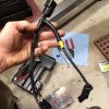
Also, I noticed the wires coming out of this round, black device are coded different than my original and the order of two of the pins is different as well, so I swapped them to match the original harness.

IMG_8014.JPG

IMG_8016.JPG

After I doing that I realized that there was no mention of this particular harness in Growlerbearnz's instructions. Was I supposed to do that???
 
That's correct- the instructions are for both plugs on the IP, I only took photos of the square one. I've updated the post to make it more clear.

would it be ok to just run a jumper inside the plug if I could manage it?
Grounding the tachometer wire- I'd avoid making connections inside the plugs, the factory crimps and rubber grommets are designed to deal with constant vibration, if you add wires and/or solder it's going to make it less resistant to vibration. It's probably not a huge deal, but connecting the two black wires on the harness itself is quite convenient and easily reversed. Slip the plain tube down the harness to expose the wires (around where the yellow tape is in your picture). Use a sharp knife to peel a small section of the insulation back, twist the two wires together, solder to fix, and wrap the join with tape.
 
Last edited:
That's correct- the instructions are for both plugs on the IP, I only took photos of the square one. I've updated the post to make it more clear.


Grounding the tachometer wire- I'd avoid making connections inside the plugs, the factory crimps and rubber grommets are designed to deal with constant vibration, if you add wires and/or solder it's going to make it less resistant to vibration. It's probably not a huge deal, but connecting the two black wires on the harness itself is quite convenient and easily reversed. Slip the plain tube down the harness to expose the wires around where the yellow tape is in your picture. Use a sharp knife to peel a small section of the insulation back, twist the two wires together, solder to fix, and wrap the join with tape.

Thanks, GB! And yes, your solution is definitely the simplest way of going about it. Took me 10 min. with a soldering iron. Wrapped it up and can't even tell. I have a feeling the original harness was done the same way, albeit with a separate, dedicated ground wire.

IMG_8029.JPG

IMG_8030.JPG
 
Spoke with Kats Heaters today about the applicability of their lower radiator hose heater to this engine. The guy said because of the close proximity to the thermostat, there was a good chance it would work fine as the internal thermostat of the 600 watt heater is 250 degrees and would likely open the engine thermostat to let the warm coolant into the engine, but there are no guarantees. He said the frost plug heater is their most efficient block heater and would be more ideal and in all weather conditions. So, I think I will stick with the frost plug heater. I also realized the heater I got, model 10401 will fit the engine, but there is a more updated version, model 11401, with a removable plug that I think I will order. They are only $25 ea. so no biggie.
 
The new alternator has a different 2-pin connector so I removed the terminals from each connector block with the idea of simply swapping the connectors. Unfortunately the female spade terminals from the Delica harness were a slightly different style and wouldn’t slide into the connector block for the new alternator harness, so I removed the connectors from the new harness and soldered them onto the old harness and then slid them into the new connector block. Done.

I thought about just cutting the old connector off the harness and splicing on the new harness with a pigtail, but the wire gauge on the new harness was considerably smaller than that of the Delica harness and it's usually not a good idea current-wise to splice on a reduced wire gauge so exchanging the terminals made more sense.

Original alternator.
D8255E46-F725-482D-9D92-30863AA6D28B.jpeg

New Alternator.
91F3F8D2-14AB-43D8-87C9-0BE22892A74A.jpeg

Delica harness with terminals removed and connector labeled accordingly.
FB0160D0-1E07-4C5E-9F61-1D2DB5E95401.jpeg

New harness with terminals removed and connector labeled.
F1595401-354A-40E4-8B54-CFD3C7B2951B.jpeg

Old and new connectors side by side.
663B5108-2E61-4DEE-9A9B-F09A651F5813.jpeg

New connector installed on Delica harness.
373EAFF5-2565-4CAF-B64E-2FC043259D96.jpeg

(Working on the electrical conversion/compatibility stuff has given me even more appreciation for Growlerbearnz's having blazed the trail for this project. I'm not sure I would have had the presence of mind to do a comparison for the circuitry on the harnesses.)
 
Last edited:
Top